|
Spallation
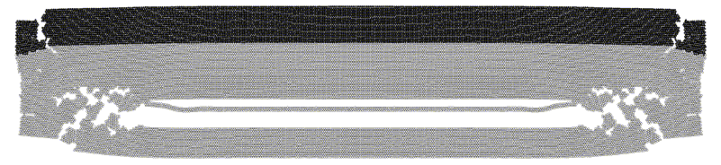
Spallation experiments produce a simple deformation at very high strain rates, which makes these experiments to be essential tool for testing material properties and validating general theoretical models. Pictures show the computational model for the impact experiment on spallation, where the particle's configurations before and after impact are shown. The particles are filling two rectangles, representing the impactor and the target. Initially the target has zero velocity, the impactor has a constant velocity directed towards the target. Free boundary conditions on all boundaries are applied, which allow observing boundary effects varying significantly for the different particles arrangements. The spall crack is appearing in the target due to superposition of shock waves reflected from the free surfaces of the inpactor and target. For more information the following papers can be downloaded
| |
Perforation
This approach is used in order to simulate perforation of plate targets by rod projectiles. Pictures show the model of the 2D computer experiment simulating oblique perforation. In the initial position ogivenose projectile (black color) in nearly touches the target (gray color). The velocity of the projectile is directed along its axis of symmetry, which is 30 degrees inclined from the direction, orthogonal to the target. The impact velocity is 1.3 km/s, length-to-diameter (L/D) ratio of the projectile is 8.6, and target thickness divided by the original projectile length (T/L) is 0.32. Presented pictures show sequential stages of the impact corresponding to 0, 8, 19, and 42 mks after the impact beginning (please click at the images to enlarge them.) Wear of the projectile, crater formation, debris sputtering, and the projectile yaw are clearly visible and they are in a good agreement with well-known experimental results. For more information the following paper can be downloaded
You can also download a small MPEG movie illustrating the perforation process. | |
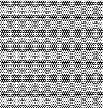
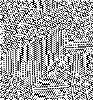
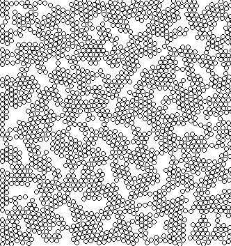
Polycrystals creation
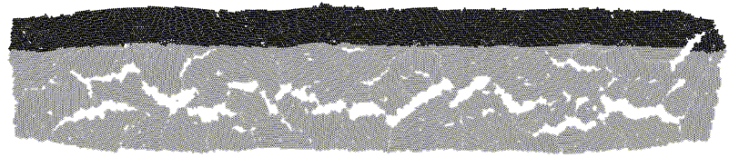
One of the main challenges in use of molecular dynamics technique for simulating macroscopic behavior of materials is that all regular particle packings produce computer materials with anisotropic mechanical properties. This can be the reason why molecular dynamics, which is widely used in modeling crystalline materials, still has limited applications in the case of homogeneous isotropic solids. The approach, which allows bypassing this problem, is to construct polycrystalline particle packings with random distribution of the monocrystal grain orientations. This method can produce isotropic computer materials, which can satisfy to very wide range of mechanical, thermodynamic and physical properties. Recent advances in nanotechnologies also stimulated molecular dynamics aided research in the area of nanocrystal materials. One of the possible variants for creation of the polycrystalline computer material is the compression technique, where a mixture of the random grains is being compressed uniformly in all directions, as shown in the top figure. Under compression the grains consolidate and form a porous material. Examples of the polycrystalline computer materials with different porosity are shown in the figures (a-c), where for the better visibility negative colouring is used - white for material and black for voids. Each 2D pattern consists of approximately 100 thousand particles. Zoom-up enlargement of a small area inside each pattern is provided to visualise the material structure, where individual particles can be identified. Pictures (a), (b), (c) corresponds to 20%, 10%, and 1% porosity respectively. After the material with the required porosity is prepared it can be used in various computer tests to determine its elastic and strength properties. For more information the following paper can be downloaded
| |
Static experiments with polycrystals
Stress-strain relations for mono and polycrystal specimens are compared in the left picture. From the graphs it is clearly visible that strength for the monocrystal material is much higher then for the polycrystal ones. Moreover, monocrystal material shows brittle behaviour, where the polycrystal specimens are more ductile. Strength, Poisson coefficient, and Young modulus of the polycrystals as functions of porosity are depicted on the right picture. Values of all these mechanical properties decrease when the porosity of the material increases. For more information the following paper can be downloaded
| |
Dynamic experiments with polycrystals
Please click at the images to enlarge them. The computer experiments show that the polycrystalline computer materials can possess in the impact processes the behavior, which is strongly different from those for the monocrystals. The main feature of the polycrystals is smearing the shock waves due to heterogeneity of the granular structure of the polycrystals. This leads to decreasing the localization effects, which are usual for ideal monocrystals. Material porosity introduces additional resistance for the shock wave penetration in the material. The speed of the shock wave penetration is smaller for the more porous material, and the relation between the shock wave speed and material porosity is close to linear. Free surface velocity is decreasing sharply for the higher porosity, which practically means that all the energy of the shock wave can be easily dissipated in the porous material due to the plastic deformations caused by the pore collapsing. This also is proved by the fact that no spallation was observed in the highporous materials at the impact velocity, which easily breaks the monocrystal target. Thus in this point the porous material is much stronger then the ideal crystal, since the porous material can absorb energy due to the strong plastic deformations in its microstructure. But obviously this conclusion corresponds only to more or less plate impacts; for example in the case of sharp indenter the strength of the porous material is far less then for the material with low porosity. For more information the following papers can be downloaded
| |
Application for percussive drilling
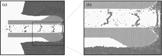
To illustrate the practical application of the percussive drilling methods a slide from a computer simulation showing a downhole tool penetrating rock is presented in the picture. The drilling is performed by a traditional hammer bit, but with percussive enhancement. From the simulation it can be clearly seen, how periodic impacts increase the material fracture. The light grey colour specifies cross-section of the hammer bit, which has an axial channel used for debris removal; dark grey colour specifies the rock being drilled. The simulation itself allows examining the majority of physical phenomena such as wave propagation, compaction, development of cracks and forming the debris, and dynamic progression of the tool in the drilled rock. For more information the following papers can be downloaded
Additional information about percussive drilling technique can be found at the Vibration Enhanced Drilling Research Group web site (VED RG). | |
Further information
 ........
 ...
...